We finally have testing results in regard to our ankle system! While we were 100% sure that the system was capable of moving the mass of our user’s foot, we had not had any real lab data on the capabilities of our ankle system until now.
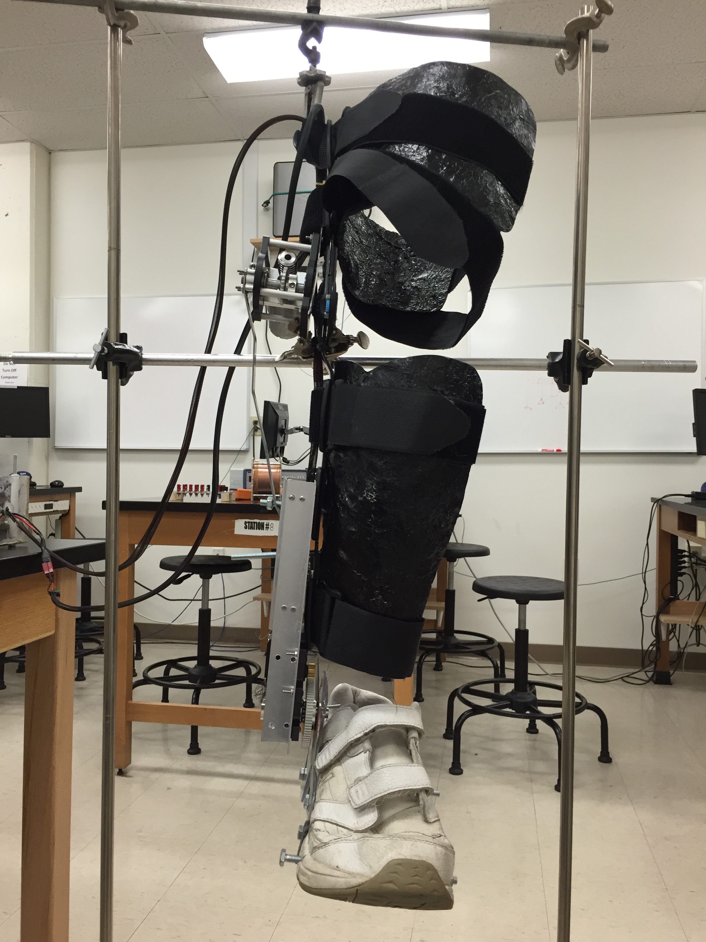
The physics department allowed us to use materials for testing. Here is the leg brace firmly held in place allowing us to test the torque output of the ankle system
We evenly distributed weight through the shoe seen above and tested to make sure that the system still maintained the full range of motion required. We first added 0.5kg to the shoe and increased the weight in 0.5kg increments all the way to 5kg (5 times the mass of our specification) while still maintaining the full range of motion. Although our testing format was rather simple, it provided us with data proving the validity of the ankle system design.
Below is a video of the ankle testing in progress. The angle of rotation in the video is far beyond that which is required by specification and even beyond normal ankle motion, but it allowed for very thorough testing of the system.
While we were in the physics lab we decided to weigh our system to make sure that it was under the 4.5kg for the leg and 6.8kg for the box that was required by our specification in order to make it easy for our user move as needed. Below are the masses of the box and leg brace respectively.
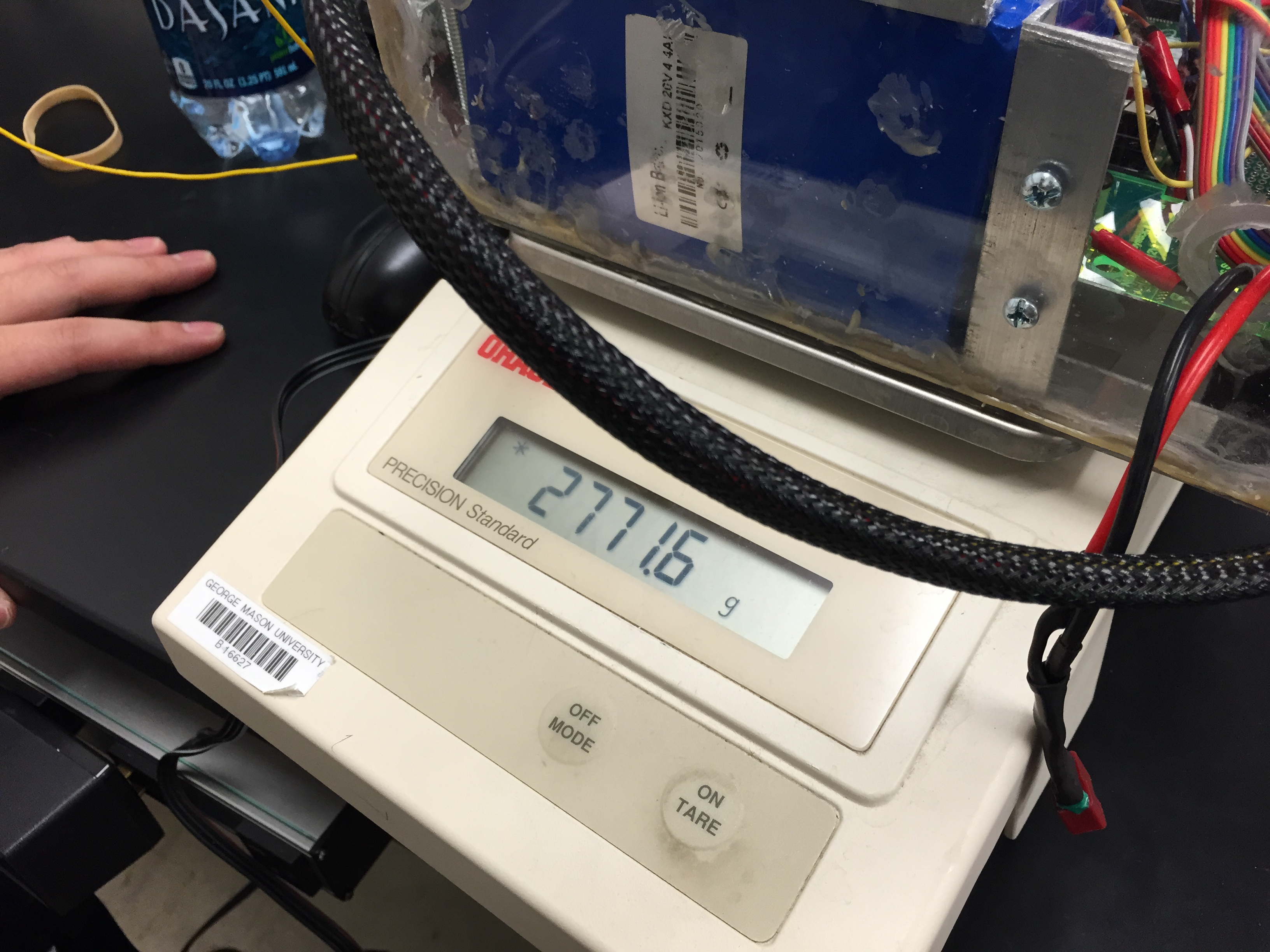
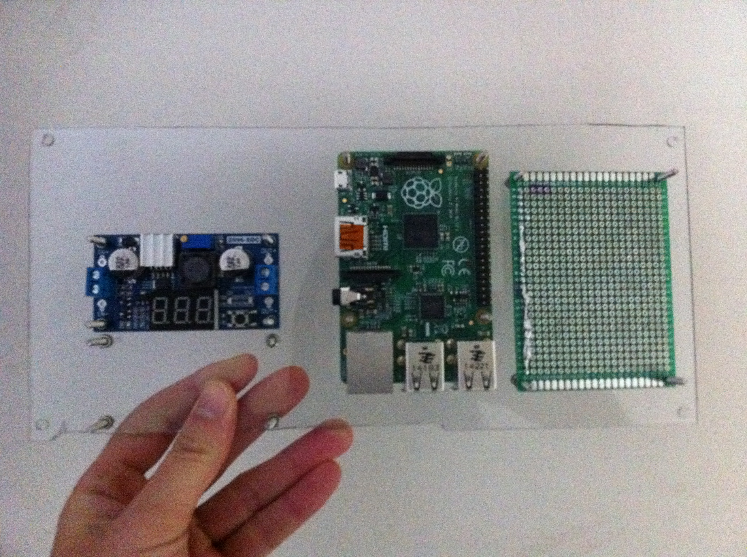
Here we weighed the box containing all hardware components of our project aside from the leg brace and it came out to be only 2.7716 kg.

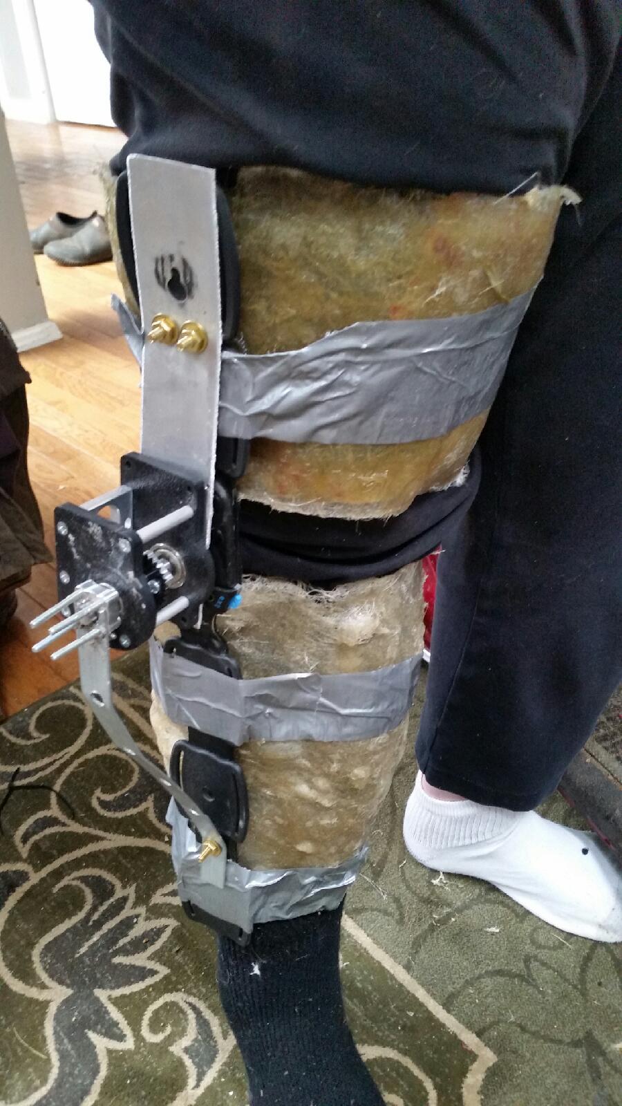
Here we weighed the completed leg brace and to our surprise it came out to be only 2.7146kg.
Cumulatively our system only weighs 5.4862 kg which is fantastic! It is far below the user’s max which means it will be very easy to move around.