
We’ve completed a first iteration of the leg brace and delivered it to the user. Video and pictures should be coming soon (since the user will be interacting with the leg brace this weekend).
In the meantime, the following are some updates:
In a previous entry, we showed the box enclosure, which will hold the control system and other hardware and direct various wires. We’ve designed a shelf to hold the hardware components so that they won’t move around as the user carries the box (the box will have straps so that the user can carry it like a backpack).
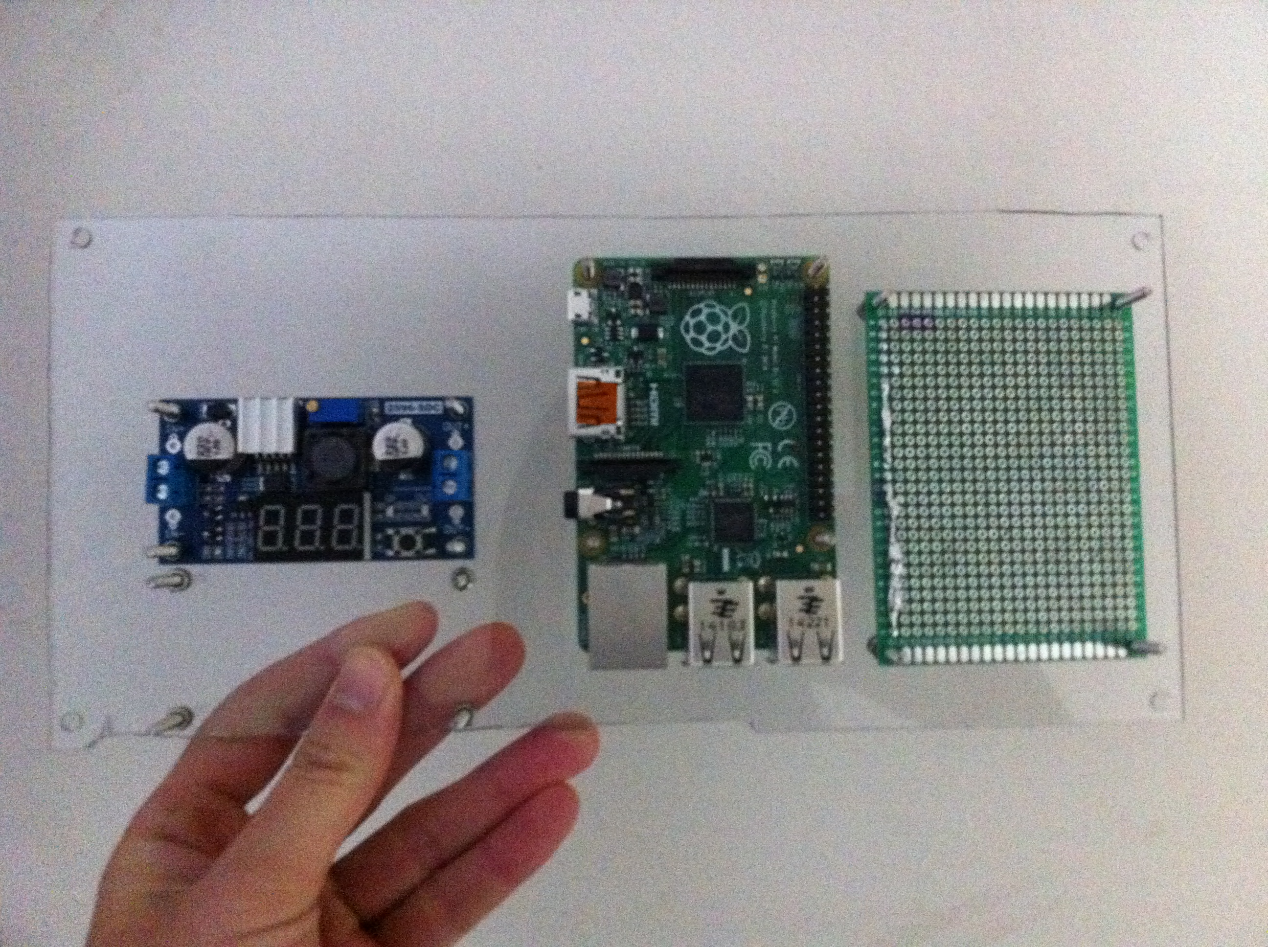
A shelf to go into the box enclosure where all parts (the RPI, the vector board, etc.) are bolted down.
We also made a carbon fiberglass leg mold. First we made a paper mache mold. Using that, we made a carbon fiberglass mold of the leg. We can mount the motors directly to the mold. Also, the fiberglass also provide structure. Instead of the user having to use several straps of velcro to attach the brace directly onto their leg, they can take the fiberglass on and off since the motors, leg brace, etc. will be attached to the fiberglass.

We made a fiberglass mold to mount the motors onto and to provide structure for the leg brace.