Despite not updating since last December, we have several updates.
We got a new knee motor. While it has a slightly lower torque output than our first knee motor, it has a greater RPM, making it better for knee movement.
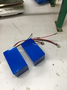
We finally decided and ordered a battery.
It is 12 V, 20 A-h battery (with a 10 A PCM [protection circuit module]). We’ve confirmed the voltage output (12.7 V) with a voltmeter. When the battery was hooked up to the knee motor, the free running current was 0.3 A knee. When the battery was hooked up to the ankle servo, the free running current was 0.5 A for ankle servo. When the battery was connected to a 100 Ohm resistor, the resistor blew up.
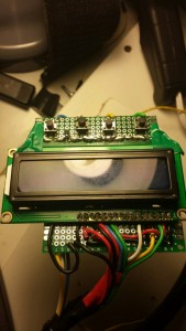
We redesigned the armband circuit. The LCD screen now shows the modes and the LEDs have been done away with. This removes the usage/need of Charlieplexing.
The LCD circuit currently displays information about the modes. It doesn’t yet display the battery life because we haven’t completed the battery monitoring circuit.
We developed a leg mold so that the user doesn’t have to deal with all the straps on the leg brace. Instead of dealing with the multiple velcro straps, the user can put on the leg mold, which provides structure and housing for the leg brace, the motors, etc.
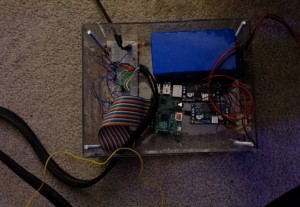
We made an box enclosure to hold the control system, hardware, and battery. The various wires are in braided sleeving so that they don’t get tangled. There are three main sleeves: one for the knee motor, the ankle servo, and the armband circuit.
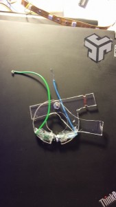
We were finally able to design a toggle input handle that matches the user’s specifications. The following is a prototype of the handle. We have a improved design that’s been 3D printed, but we don’t have images of it yet.

The “ends” of the “R” would be extended so that they make a handle that the user can grip. The wires got to the RPI. There is a pivot point so that the contacts can connect (by squeezing the handles).
This was modeled after a bike brake.
More updates and photos will be coming shortly!


