Tag: progress report

Armband level up

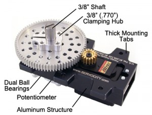
We have good news and bad news. Part one of the bad news is that our knee motor broke. Our knee system uses a worm gear and regular gear; as we mentioned in the last entry, the regular gear is made of plastic and got stripped. In the meantime, we’ve ordered replacement plastic gears so …

Continue reading

Leg brace shown to the user

We’ve started integration for our project. The fiberglass mold has been completed and we were able to incorporate that into the overall brace. We made two fiberglass molds: one of the upper leg and one for the lower leg. As one can see from the photo, the molds are a little rough around the edges, …

Continue reading

Design details

We’ve completed a first iteration of the leg brace and delivered it to the user. Video and pictures should be coming soon (since the user will be interacting with the leg brace this weekend). In the meantime, the following are some updates: In a previous entry, we showed the box enclosure, which will hold the …

Continue reading

Many updates

Despite not updating since last December, we have several updates.

Continue reading

Battery progress

The battery group is responsible for the powering the system. We decided to use a 12V 10Ah rechargeable battery. It should power all parts (maximum output) for two hours. The parts that need to the powered are: the control system (Raspberry Pi, 5V), LCD battery display (5V), ankle motor (6-7.4V), and knee motor (12 V). …

Continue reading

Armband progress

The armband system is responsible for receiving user input and displaying it back to the user via an LCD screen. The system is composed of buttons, LEDs, and an LCD. The LEDs display the state of the system to the user and are implemented via Charlieplexing in order to reduce the number of GPIO pins …

Continue reading

Knee progress

The knee subsystem is responsible for rotating the knee portion of the leg brace. It uses a gear motor that interfaces with a vertical worm drive gearbox in order to rotate a shaft that has an arm that is attached to the gearbox system and the brace to move the leg. The knee motor is …

Continue reading

Ankle progress

The ankle subteam is responsible for designing an ankle brace that will simulate movement for the user. The torque for ankle was calculated using T = m*g*l. The torque was calculated as T = 3.4 N*m. A 20% safety margin was used, increasing the required torque to 4.08 N*m. The selected servo has a maximum …

Continue reading

Control system progress

The control system is responsible for processing and directing the signals of the our system. We have a variety of user inputs, which are sent to the system via buttons. The inputs are then go to an information display, which show whether the system is in automatic or manual mode. If it’s in manual mode, …

Continue reading